Technical Guide | Plate Pack Engineering | Replacement Parts
A plate heat exchanger plate arrangement drawing is much more than a list of metal plates. It is the equipment-specific map that tells a maintenance team how the plates, gaskets, ports, and flow passages belong together. Understanding that map is essential when ordering aftermarket replacement plates, rebuilding a plate pack, investigating unexpected pressure drop, or preparing a major service shutdown.
This guide explains the information buyers should look for in a gasketed plate-and-frame heat exchanger drawing, including A/B plate orientation, plate handedness, open and closed ports, flow passes, special plate positions, and the compressed plate-pack dimension. The examples are general educational references, not instructions to operate or reassemble a particular pressure-containing unit without its approved manual.

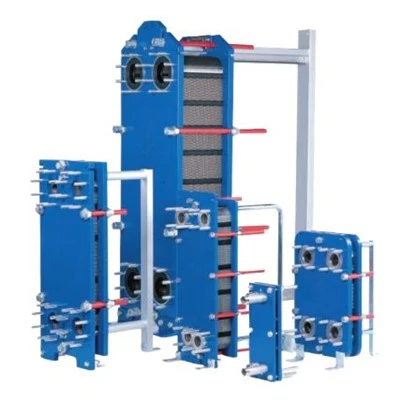
General heat-transfer plate photograph from our existing product imagery. A plate photograph is useful for identification, but it is not a substitute for a model-specific arrangement drawing.
In this guide1. What Does a Plate Arrangement Drawing Actually Show?
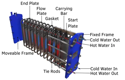
A gasketed plate heat exchanger consists of a stack of formed metal plates supported by a frame and compressed between a stationary frame plate and a movable pressure plate. Gaskets around the plate perimeter and selected ports guide the hot and cold fluids into alternating channels. The two streams are intended to stay separated while heat passes through the metal walls.
The arrangement drawing connects these individual components to the operating design. Depending on the manufacturer, it may show the direction in which the plate pack is viewed, the order of plates from the fixed end to the movable end, the plate type used at each position, the gasket-facing direction, port punch codes, and the routes taken by both fluids. A full drawing package may also identify connection positions, individual plate quantities, material grades, and the final closing dimension.
For procurement, this distinction matters because a model name describes a family of equipment, while the arrangement drawing describes a particular installed configuration. Two exchangers with the same frame family may have different plate counts, flow passes, port arrangements, or combinations of thermal patterns. Ordering solely by the exchanger model can therefore create a mismatch even when the replacement part looks similar to the old plate.
Core principle: Identify the complete equipment and installed plate arrangement before concluding that an individual aftermarket plate is compatible. The brand or model number alone may not describe every required plate position.
2. Which Documents Should a Maintenance Buyer Collect?
Start with the original general arrangement drawing, plate arrangement drawing, nameplate, and any plate identification schedule supplied with the exchanger. These documents answer different questions. The general arrangement identifies connection locations, physical dimensions, and installation orientation. The plate arrangement indicates the internal sequence and flow routes. The nameplate may record the equipment type, serial number, and rated operating envelope. A maintenance history shows whether plates were previously removed, replaced, or reconfigured.
Old installations often lack a complete document package. In that case, it is useful to photograph the exchanger from the fixed-end side, record all readable numbers, identify the port positions, and make a controlled inventory of the existing plate types before parts are ordered. A qualified service team may need a representative plate sample or a detailed drawing when original identification is missing.
| Document | What It Can Confirm | Why the Buyer Needs It |
|---|---|---|
| Equipment nameplate | Manufacturer, full model, serial reference, and rated conditions where shown | Prevents confusion between different equipment families and legacy variants |
| General arrangement drawing | Fixed and movable ends, nozzle positions, dimensions, and installation orientation | Confirms which physical connection and frame end the drawing describes |
| Plate arrangement drawing | Plate order, orientation, port codes, gasket direction, and pass routing | Defines which replacement plate belongs at each position |
| Parts or plate schedule | Plate patterns, materials, quantities, and special positions | Separates standard channel plates from turning and terminal arrangements |
| Maintenance record | Past repairs, observed leaks, plate-count changes, and earlier closing measurements | Highlights differences between the original design and the unit now installed |
Manufacturer-specific documentation takes precedence over a generic aftermarket catalog. If the original drawing and the current equipment disagree, investigate why they disagree before approving a new plate pack. The difference could result from an authorized retrofit, a past maintenance error, or an undocumented replacement.
3. What Are A Plates, B Plates, Right-Hand and Left-Hand Plates?
Many gasketed exchanger manuals use A and B to describe alternating plate orientation. In a typical arrangement, one plate is turned relative to its neighbor so that the corrugations meet at appropriate contact points and produce the intended flow channels. This often creates a recognizable alternating edge pattern in the assembled pack. The exact visual marking and orientation convention, however, belong to the equipment manufacturer.
Other manuals identify right-hand and left-hand plates, or describe which side of a plate faces the stationary head or movable follower. These terms may refer to the direction of the chevron pattern, the flow routing, or a specific plate designation. They must not be interpreted using a rule borrowed from another brand. Even when two plates have the same outer profile, they can differ in gasket direction, punched ports, or the role they perform in the plate sequence.
How to read the orientation information
First confirm the drawing's viewing direction. A right-hand designation viewed from the fixed frame side may not look the same as a photograph taken from the opposite side. Next identify the physical plate face, stamped model, and gasket side. Finally compare the intended position in the plate schedule. A technician should record all three dimensions of identification: which plate it is, which way it faces, and where it belongs.
Some designs can use one pressing in more than one orientation, while others require different pressings or port punches. A rule such as "simply turn the plate over" is therefore unsafe as a universal sourcing instruction. For example, diagonal-flow and vertical-flow configurations can use different handedness and port arrangements depending on the model.
Useful information on the plate
Stamped model numbers, visible chevron direction, gasket-groove shape, hanging features, and open-port positions can help distinguish neighboring variants. Always photograph both faces rather than relying on a single front-view image.
Useful information on the drawing
Look for the orientation key, the legend identifying right and left, the direction from head to follower, and the numbering of positions. Read the legend before interpreting A/B or similar abbreviations.
4. How Do Port Punch Codes and Gasket Paths Control Fluid Flow?
The four corner regions of many gasketed heat exchanger plates form distribution manifolds when the plate pack is assembled. Not every plate needs four open holes. Certain positions may have one or more ports closed or shaped differently to route liquid through the correct channels. A manufacturer may express the configuration through a punch code, a diagram of open and blanked holes, or a plate part number.
The gasket pattern works with these ports to prevent the hot and cold streams from entering the wrong channels. Gasket material and shape also provide an external seal around the plate perimeter. This means a replacement plate with the correct height and width may still be unsuitable if its punched openings or gasket groove differ from the installed component.
Do not assume port numbers are universal
Different documentation sets may number ports from different viewpoints or use manufacturer-specific letter codes. A code such as one digit or five characters has no safe universal interpretation outside its original legend. Confirm which opening is the inlet or outlet from the equipment drawing, not from a photograph of a similar unit online.
When preparing a replacement inquiry, provide a full-face photograph that shows all four corner regions, a close-up of each opening, and measured horizontal and vertical center distances. Record the overall plate length and width separately. These are different dimensions and should not be combined under the vague description "plate size."
Procurement risk: A visually similar plate with the wrong port punch can redirect fluid, block an intended route, or interfere with the sealing pattern. Match the port configuration at the actual installed position, not only the exchanger's nominal model.
5. Single-Pass vs Multi-Pass: Why the Flow Diagram Matters
A flow pass is a defined portion of the route followed by a fluid through the plate pack. In a single-pass arrangement, each stream travels through its designated set of channels in one pass before leaving the exchanger. In a multi-pass arrangement, the flow is redirected so that it passes through additional groups of channels. The exact distribution depends on the exchanger geometry, port blocking, and connection locations.
Changing the number of passes changes the number of parallel flow channels available in each section and can affect channel velocity, heat-transfer intensity, and pressure drop. It may also require different turning plates or port closures. For this reason, adding a few plates, removing damaged plates, or reversing a connection is not automatically a harmless maintenance change.
The original design should specify the hot-side and cold-side flow rates, temperature program, allowable pressure losses, and plate arrangement. A proposed change must be reviewed using those operating conditions. Multi-pass configurations are not inherently superior to single-pass designs: a longer flow path can help meet one duty but create excessive hydraulic resistance in another.
Connection positions can provide clues
Some single-pass exchangers place all process connections on the stationary frame plate, while particular multi-pass designs use connections on the movable pressure plate as well. This is an identification clue rather than a universal classification rule. Always consult the actual general arrangement and flow schematic before identifying the pass pattern from the external piping alone.
For replacement sourcing, describe whether the request is for a regular channel plate or a special plate associated with a pass change. Where the original drawing is unavailable, ask the service engineer to verify the functional position before ordering. The supplier should not infer it from the model series or plate area alone.
6. Start Plates, End Plates, Turning Plates and Other Special Positions
Most plate packs contain a substantial number of regular heat-transfer plates, but the terminal regions and flow-turning locations may contain special configurations. A start plate or end plate can have a different gasket arrangement from a central channel plate. A turning plate may employ a particular set of open and closed ports to direct a stream into its next pass. Some equipment also uses divider plates, connection grids, or other manufacturer-specific components.
These names are descriptive, not interchangeable part numbers. Their exact geometry and functions vary by design. An individual plate purchased for a middle position may not be suitable for the first or final position even when the chevron pattern seems identical. Matching gaskets also may differ because the fluid needs to be sealed differently around particular ports.

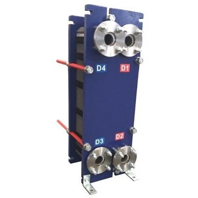
General replacement plate illustration. Distinct start, end and turning configurations must be identified from the actual equipment drawing.
A clear purchasing schedule should identify plate quantities by each configuration, not merely state the total number of metal plates. This is especially important when a complete plate pack is being renewed after many years of service. Use a separate line for every different material, pressing pattern, port punch, gasket arrangement, or special location where relevant.
In difficult legacy applications, the buyer may supply original plates as reference samples. Samples should be marked with their installed positions and protected against bending or surface damage during transport. An aftermarket supplier may be able to review the components, but final interchangeability should not be promised until all critical features have been confirmed.
7. What Is the Plate-Pack Closing Dimension or A-Dimension?
The compressed plate-pack dimension is the specified distance associated with the assembled and tightened plate package. Some equipment manuals call it the A-dimension, while others use a different designation. It is a controlled mechanical requirement tied to the frame, plate count, plate design, and gasket system. It should not be guessed from a photograph or copied from another exchanger using a similar model name.
Correct compression helps the gaskets form their intended seals while keeping the plate pack and frame within the permitted mechanical range. Too little compression can contribute to leakage. Excessive compression can damage gaskets, metal plates, or support contact areas. An apparently leaking unit should therefore never be tightened beyond its approved limit as a substitute for diagnosing the problem.
The closing dimension is not a substitute for an assembly procedure. The service organization must also use the model-specific tightening sequence, appropriate bolt condition, frame alignment checks, and approved inspection or pressure-testing method. Pressure-containing equipment must be isolated, depressurized, drained, and made safe by qualified personnel before it is opened.
Why plate-count changes require engineering review
If the number or types of plates change, the original closing dimension may no longer apply. The thermal area, number of channels, pressure drop, and compression arrangement may also change. The correct outcome is not to multiply a generic plate thickness by the number of plates. Obtain a revised, approved specification covering the actual configuration before any modification is accepted.
Safety boundary: This article does not provide tightening torque, bolt-turn counts, pressure-test levels, or a universal A-dimension. Those values must come from the manufacturer or an authorized engineering procedure for the particular exchanger.
8. How Plate Corrugation Patterns Influence the Arrangement
The plate schedule can contain more than one thermal pattern, sometimes called higher-resistance and lower-resistance plates or identified by another manufacturer-specific code. The chevron angle, corrugation spacing, pressing depth, and channel pairing affect local turbulence, heat transfer, and hydraulic losses. Two patterns may belong to one authorized exchanger design without being directly interchangeable as individual components.
During refurbishment, maintain a record of which pattern is located at each position. Do not assume that a plate with a similar external profile can replace another pattern merely because it fits on the carrying bar. Mating contact points and gasket seals must also be suitable. A change can influence both thermal performance and the integrity of the physical plate pack.
When the plant experiences increased pressure drop after maintenance, an incorrectly reassembled pattern is one possible issue to investigate, alongside fouling, blocked strainers, flow changes, or control-system problems. A service assessment should consider the complete operating history instead of assigning every performance deviation to a single plate.
9. Replacement Plate Purchasing Checklist: From Drawing to RFQ
For purchasing departments, the most practical way to use an arrangement drawing is to convert it into a controlled replacement-parts schedule. That schedule should specify exactly what the supplier must verify, what documents will support the match, and which differences are unacceptable. The objective is to prevent a low-cost plate order from creating a long plant shutdown because the received plates have an incorrect port or gasket groove.
Collect full manufacturer, model, serial reference and arrangement drawing.
Count plate types by position, orientation, material and punched-port pattern.
Compare physical samples, drawings, dimensions, gasket grooves and operating duty.
Agree the purchasing specification, inspection evidence and delivery quantities.
| RFQ Field | Minimum Useful Information | Procurement Purpose |
|---|---|---|
| Equipment identification | Brand, exact model, suffix, serial and nameplate photo | Locates the correct product family and equipment variant |
| Drawing reference | Plate arrangement revision, part schedule and general arrangement | Ensures all parties are discussing the same design |
| Plate geometry | Length, width, port diameter, port centers, pressed pattern and hanging points | Supports mechanical and channel compatibility review |
| Plate function | Regular, start, end, turning or other identified position | Prevents incorrect port routing or sealing |
| Material and gasket | Metal grade, thickness, gasket compound and attachment method | Checks corrosion, sealing and manufacturing feasibility |
| Operating duty | Both fluids, temperatures, pressures, flow rates, cleaning chemicals | Flags application-specific compatibility requirements |
| Scope and delivery | Quantity by plate type, destination, packaging and documents | Supports accurate quotation and incoming inspection |
Include photographs of representative original plates from the front, back, edge, port area, and gasket groove. If the equipment has been dismantled, make sure the photographs are labeled by position. When part numbers conflict among aftermarket catalogs, retain the original codes alongside the alternate descriptions and request technical confirmation rather than silently merging the records.
For recurring industrial procurement, the approved plate schedule can become a controlled spare-parts master. Store the source drawing, latest revision, material specification, observed differences, approved supplier reference and previous receipt records. A searchable master is particularly useful for sites that operate multiple brands or legacy models.
10. What Should Be Checked When Replacement Plates Arrive?
Receiving inspection should compare the shipment against the approved purchasing schedule rather than only counting cartons. Verify the declared part identity and quantity for each plate configuration. Check for transport damage, bent edges, damaged hanging points, distorted corrugations, scratched sealing surfaces, and contamination on areas that must contact the gaskets.
Where material traceability was ordered, compare the supplied certificate or agreed record with the specified alloy and batch. For gaskets delivered with the plates, verify the compound, profile, attachment features, and quantities. A correct plate with an incorrect gasket may still make the order unusable for the planned shutdown.
If a major dimensional deviation or unclear port configuration is discovered, quarantine the affected parts for engineering review. Do not modify a plate in the field simply to make it fit. Cutting an additional port, reshaping a gasket groove, or flattening a pressed feature can compromise the intended design and must not be treated as routine adjustment.
Final installation and pressure-boundary testing must follow the relevant manufacturer's procedure and site rules. Acceptance of purchased components alone does not mean that an exchanger is ready to return to operation. The complete assembly and both fluid circuits still require the checks appropriate to the equipment.
11. Typical Mistakes When Using a Plate Arrangement Drawing
Confusing model and plate variant
The exchanger model may cover different generations or flow configurations. A suffix, stamped plate code or port punch code can be decisive. Preserve the full designation instead of simplifying it for the purchase order.
Copying the wrong drawing orientation
A photograph from the movable end can reverse what the reader thinks is left or right. Identify the drawing's reference end before interpreting plate handedness or port numbers.
Ordering by a total plate count only
A count such as "100 plates" does not reveal how many are standard channel plates and how many have special ports or patterns. Require a configuration-by-configuration breakdown.
Using generic compression values
Copying an A-dimension or tightening recommendation from another unit can damage the pack. Use only the approved values and methods for the existing equipment.
Another frequent error is to assume that one supplier's model alias proves cross-brand interchangeability. Brand and model research is useful for identifying possible parts, but compatibility is established by geometry, port function, material, sealing system and the equipment's actual duty. A database should preserve contradictory references until they have been resolved with evidence.
Frequently Asked Questions About Plate Arrangement Drawings
Is an A plate always the same as a left-hand plate?No. A/B, right/left, head/follower and similar terminology can follow different manufacturer conventions. Read the equipment-specific legend and confirm orientation from the correct viewing end.
Can the number of heat exchanger plates be changed during servicing?Not as an unapproved repair. A plate-count change can affect thermal duty, channel velocity, pressure drop, flow routing and the required closing dimension. Obtain an engineering review and revised documents before changing the configuration.
Is the equipment model enough to order a replacement plate?It may identify a useful starting point but often does not establish every plate variant. Provide plate markings, dimensions, port punch information, gasket details and the installed plate position where available.
What is the difference between a port code and a model number?A model number generally identifies equipment or a plate family. A port code identifies a particular pattern of open and closed ports under the manufacturer's coding system. Both may be needed to specify the correct replacement.
Does a single-pass exchanger always have four connections on the fixed frame?Many common designs use that arrangement, but it is not a safe universal rule. Confirm connection locations and actual flow routes from the specific general arrangement and plate schedule.
Can a start plate be replaced with a standard channel plate?Do not assume so. Terminal plate positions may use different port closures and sealing paths. Match the original start or end configuration and its gasket requirements.
How do I identify a legacy plate when the drawing is missing?Collect the nameplate, detailed photographs of both plate faces, stamped marks, port measurements, hanging features, gasket-groove profile and plate thickness. A qualified supplier may request a sample or dimensional drawing for comparison.
What is the correct A-dimension for my plate pack?It cannot be established from a generic article. The approved closing dimension belongs to the exact exchanger and plate-pack configuration and must come from its manufacturer or an authorized engineering document.
Related Heat Exchanger Plates, Gaskets and Engineering Resources
Equipment owners, service companies and distributors can use this guide to prepare more complete replacement inquiries. The related resources below cover plate product families and the sealing components that belong with them. Product names and third-party brands identify intended equipment compatibility; they do not imply that independently supplied aftermarket parts are original or manufacturer-authorized.
Technical reference basis
The engineering principles discussed here are consistent with established plate heat exchanger documentation, including the ASHRAE heat exchanger handbook and published manufacturer maintenance manuals. Because plate codes, assembly conventions and pressure-boundary requirements vary among models, this article is intentionally limited to interpretation and purchasing preparation rather than model-specific assembly instructions.
Further technical references: ASHRAE Handbook, Heat Exchangers and SPX FLOW APV GPHE installation and maintenance manual .
Technical RFQ | Replacement Plate Matching
Need Replacement Plates for an Existing Plate Pack?
Send the exchanger brand, exact model, equipment nameplate, plate arrangement drawing, representative plate photographs, required plate count by configuration, metal grade, gasket requirements, and delivery country. If the installed sequence or port codes are uncertain, mention that uncertainty in the inquiry instead of guessing. We can review the information needed for an aftermarket plate-matching and quotation process; final supply and compatibility remain subject to technical confirmation.
Request Plate and Gasket Matching